During this current lockdown we have decided to have a go at robotics! Using a raspberry pi and the CamJam EduKit 3.
If you would like to know more about the raspberry pi please visit the what is a raspberry pi page.

These are the parts for building our robot. They include from right to left and down.

First we used the double sided sticky pads to attach the motors to our chassis (an old google nest mini box)

Then we attached the wheels

Next we attached the castor which is a big metal ball baring for the front wheel

We made some holes and pushed the motor wires through. Now the robot is ready for its inners

Jack first wired the motors to the motor controller

Then the battery pack to the controller
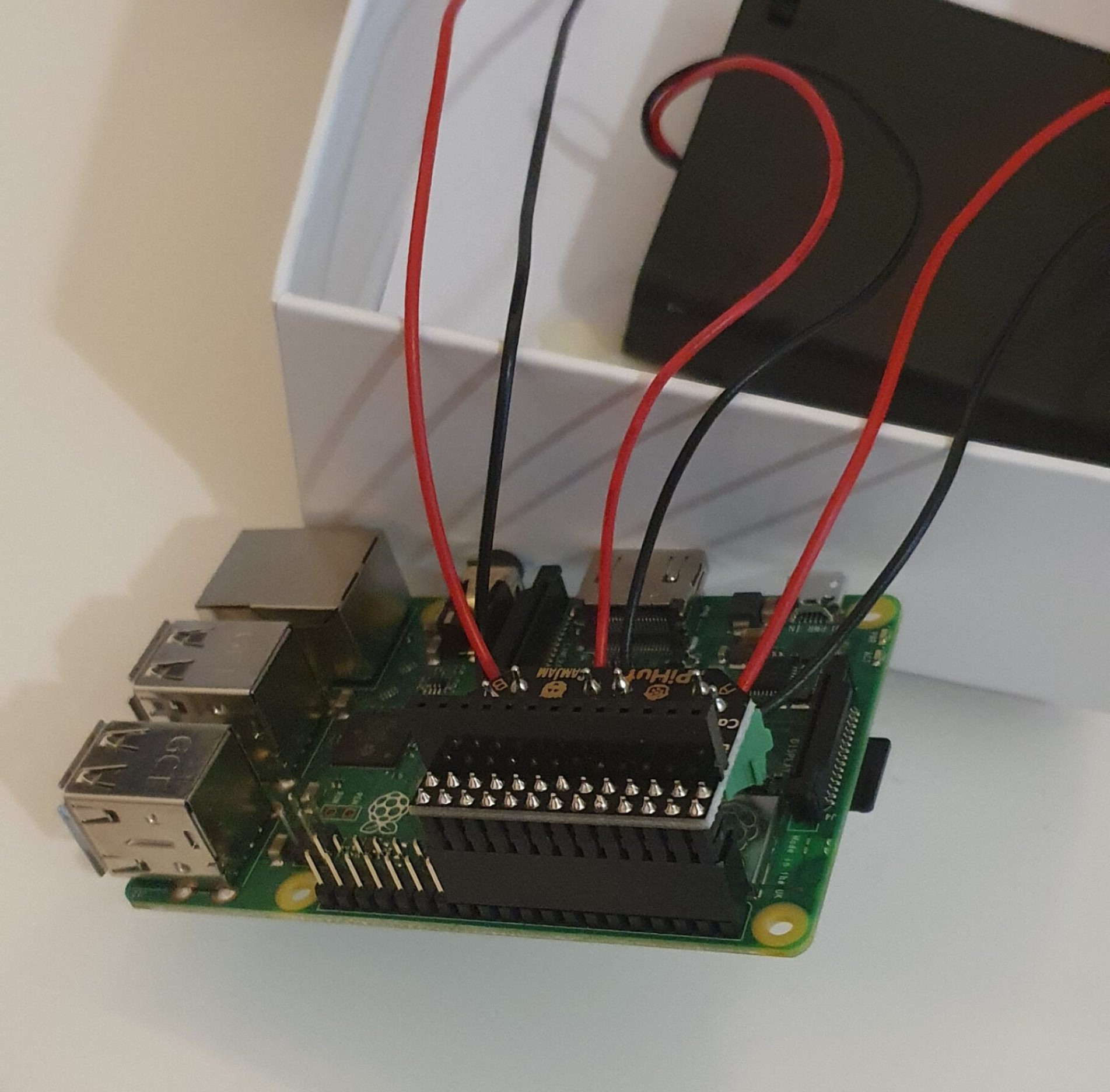
The controller slots onto the Raspberry pi GPIO (General-Purpose Input/Output) header
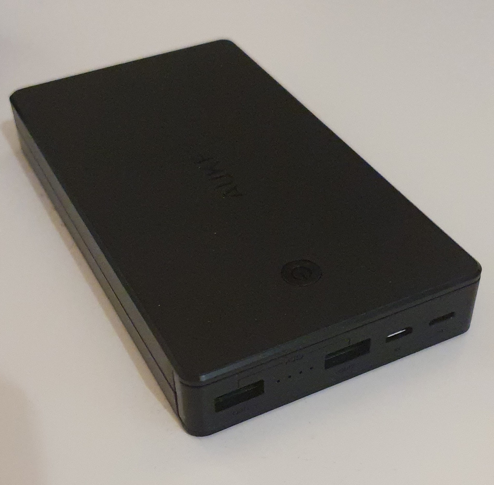
We need to add a power supply for the Raspberry pi itself. The battery pack wired to the motor controller is just to power the motors. We used an old power bank to power the pi, its a bit on the large size, we hope it will help give some weight to the robot to help the tyres grip.

Now for the coding. We power up the raspberry pi and connect to it
remotely using a MacBook. We use a programming language called
Python. It looks like this:
The first two lines of the code import libraries. Libraries are
pre-written code that enables you to write simpler code, like the
code below. You can simplify code by writing functions. Functions
are like storing many instruction in one word. This is a bit like
how some of our words work, for example if you tell someone you’re
going shopping, you know that word means a set of instruction, like
making your way to a shop, finding things you want, paying for them,
putting them in a bag and bringing them home. You do the same with
code, to simplify it for later use, make one word mean/do many
things. For example robot.left() tells the Pi to turn the power off
on pin 9 on on pin 10 off on pin 8 and on on pin 7 making one wheel
turn one way and the other the other way.
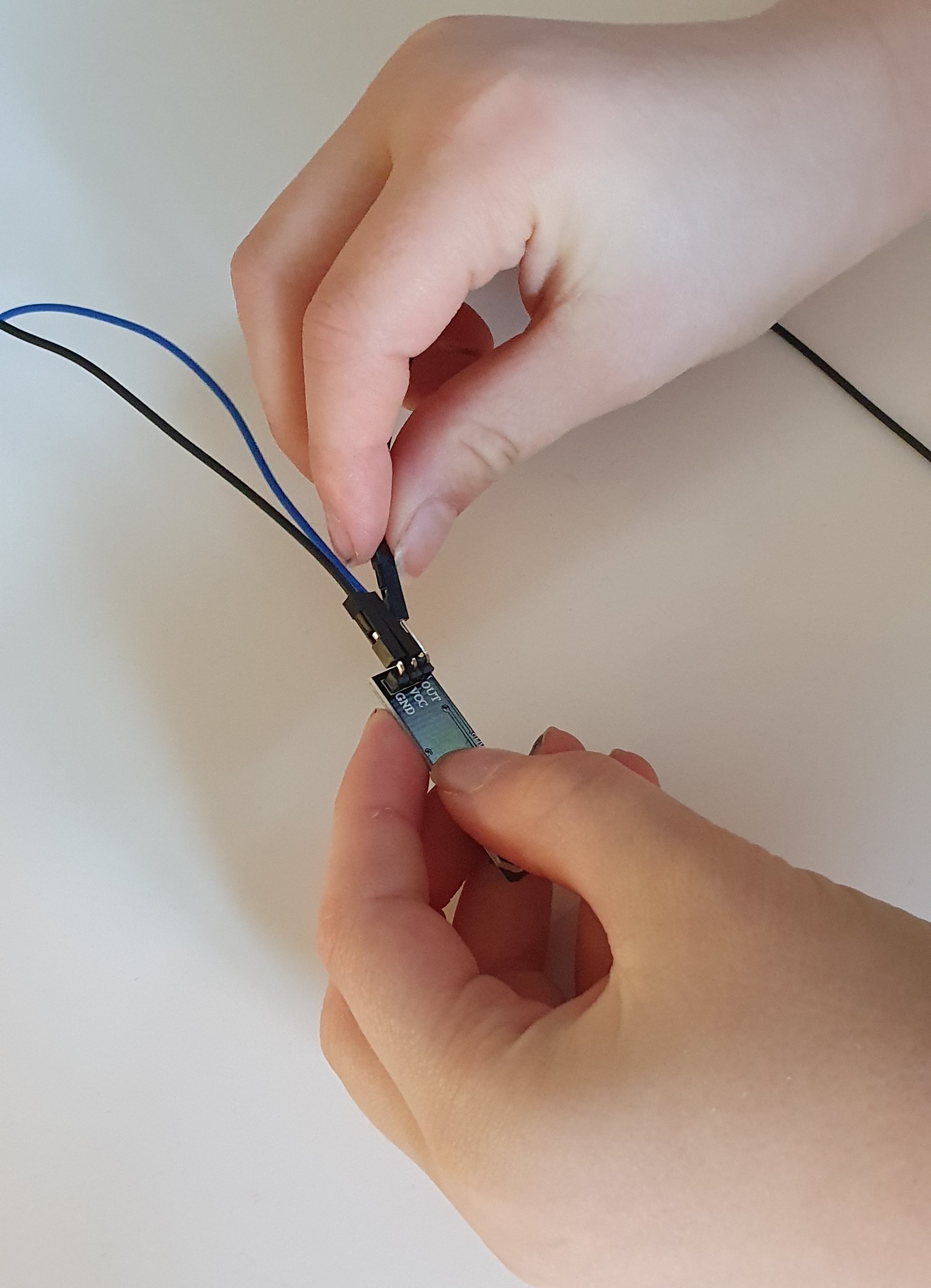
Jack attached one end of the jumper cables to the line sensor.
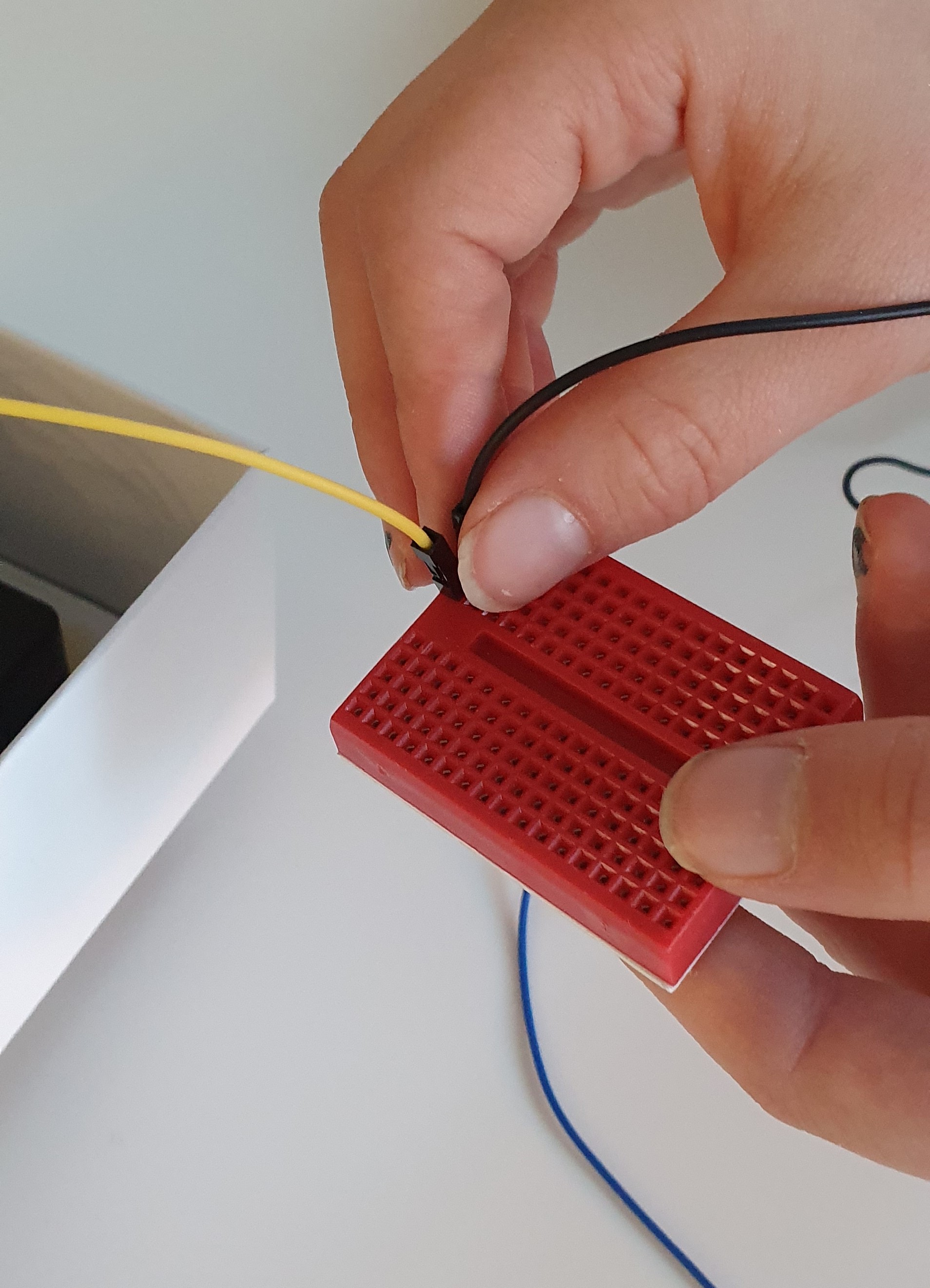
He then attached the end of one of those wires to the bread board.
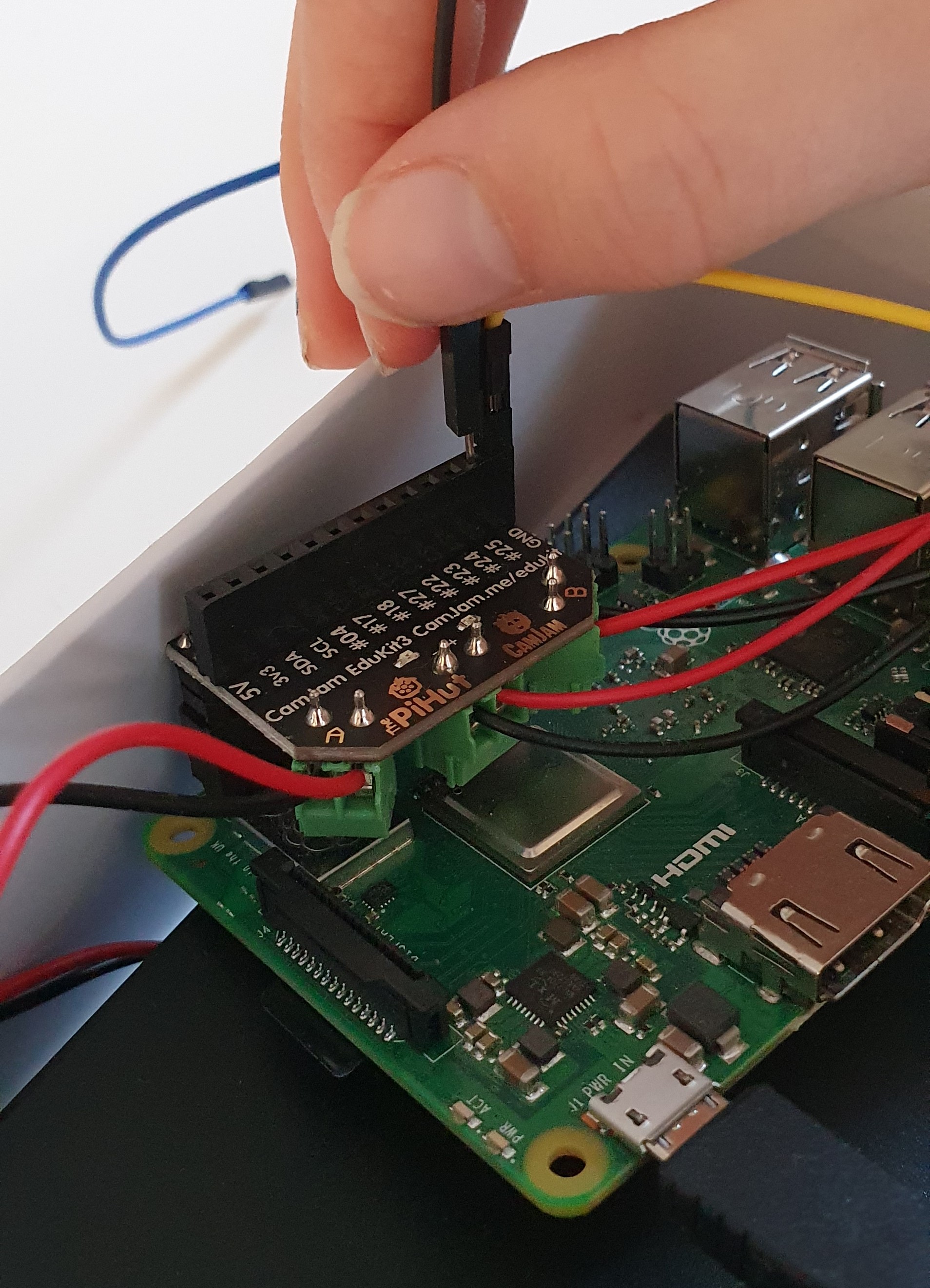
He used another to connect the bread board to a pin on the Raspberry Pi. The breadboard is a way to connect two wires together as long as they are in the same column (inline vertically).
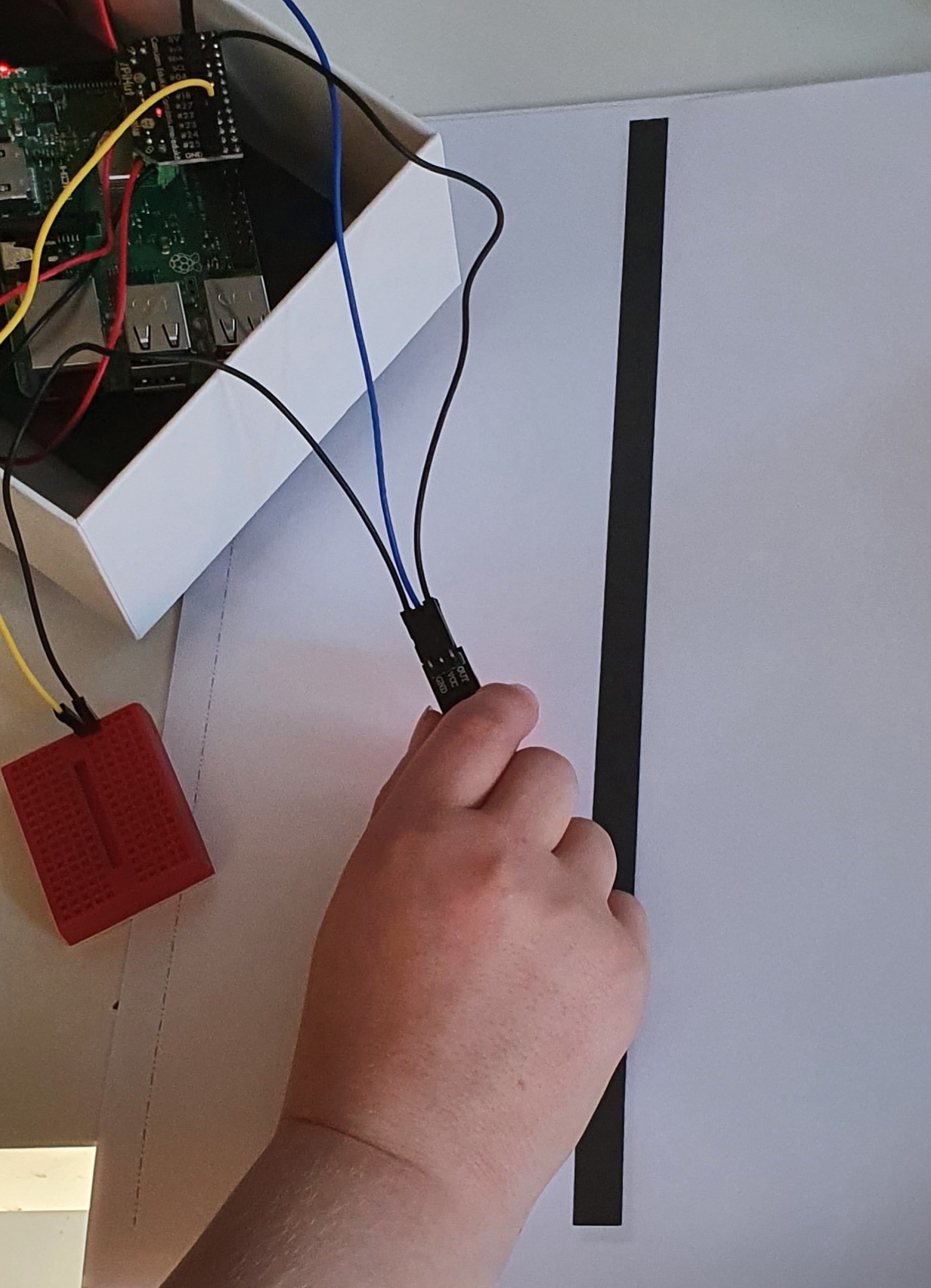
After typing up the code for the line sensor we ran some tests. Every time the sensor went over the black line “Line seen” was printed to the computer screen and when taken away from the line “Line not seen” was printed to the screen.
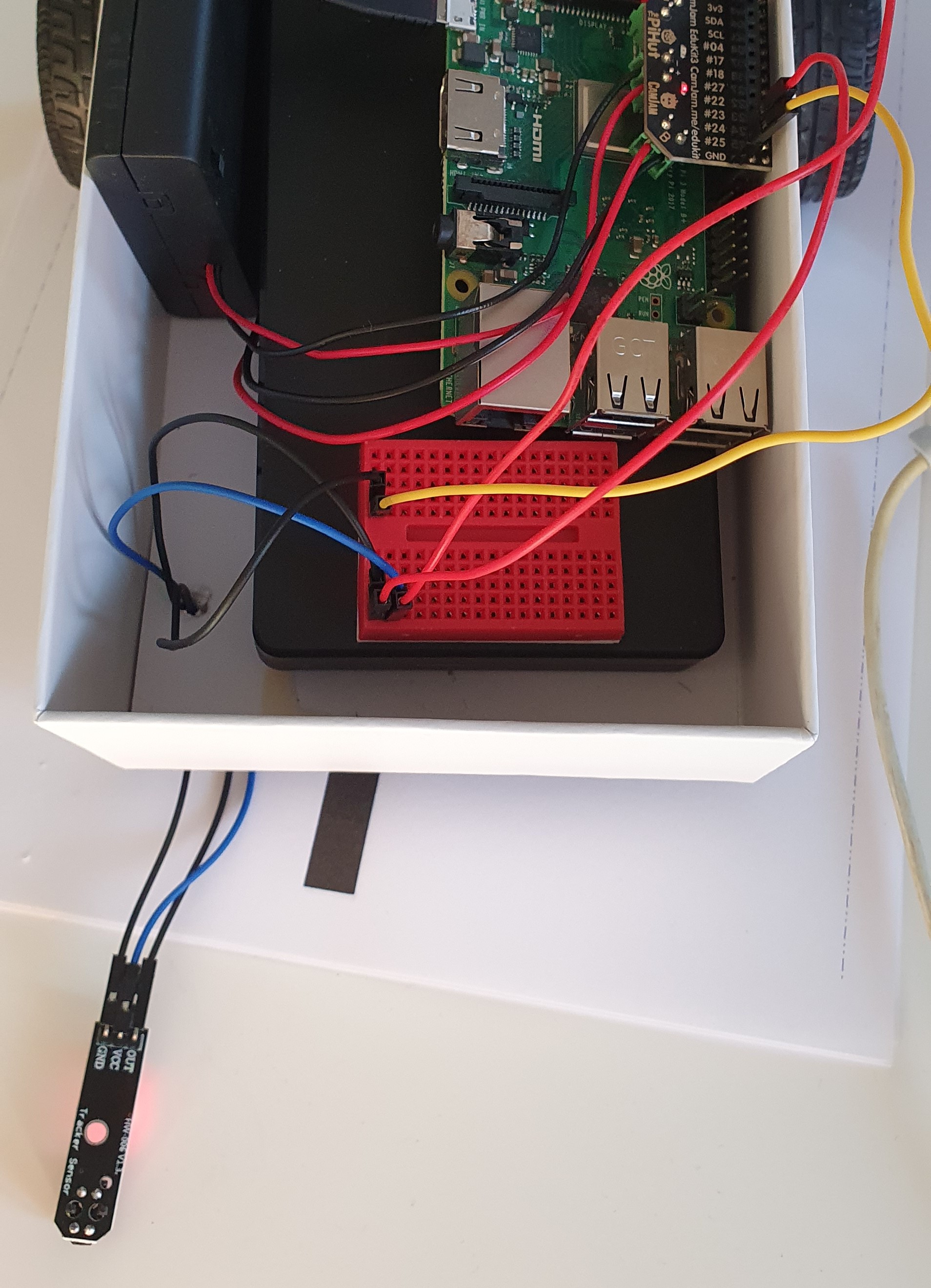
We then made a hole for the wires so we could attach the sensor to the bottom of the robot. We had to modify the wiring a little to give us more cable to reach underneath.
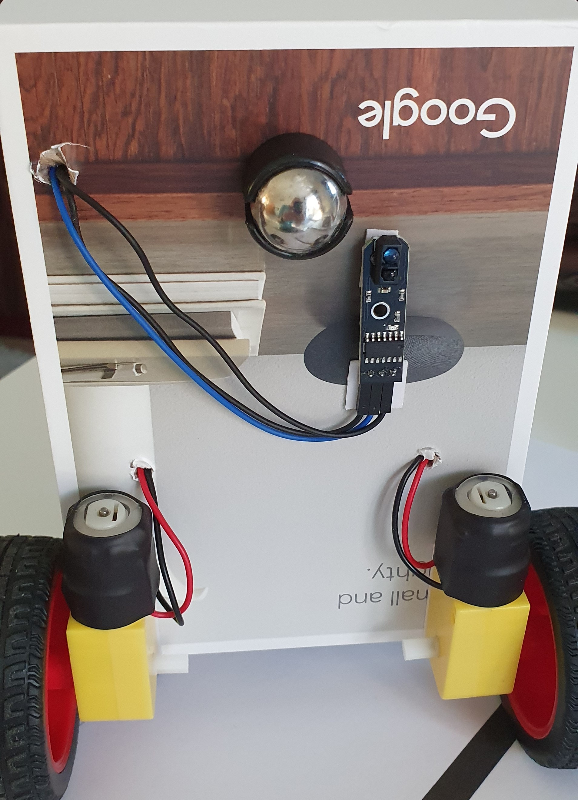
Here it is, our robot now has a line sensor!
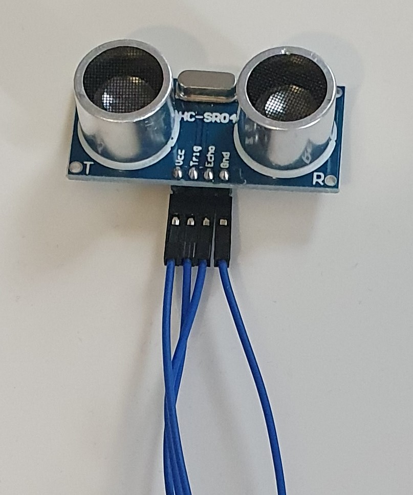
This is the ultra sonic distance sensor. It sends out a sound that’s too high in frequency for our ears to here. It then waits for the sound to bounce back off whatever is in front of it and works out how for away the something is by how long it takes for the sound to bounce back.
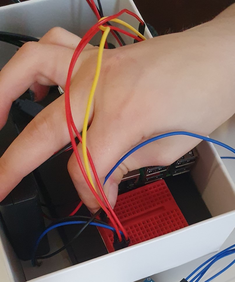
We started by connecting four jumper wires to the sensor, inserting them into the breadboard along with wires from the right pins on the Pi.
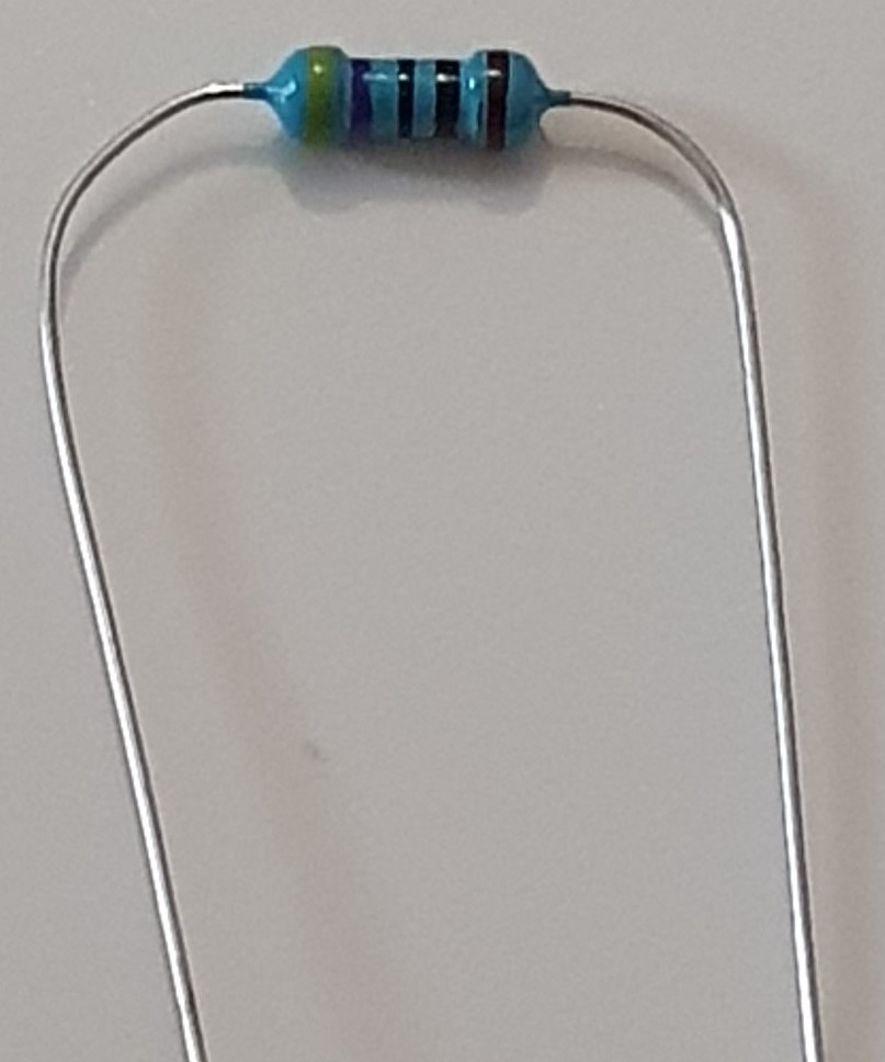
For this sensor to work we had to restrict the flow of power going to the sensor. To do this you need to use resisters.
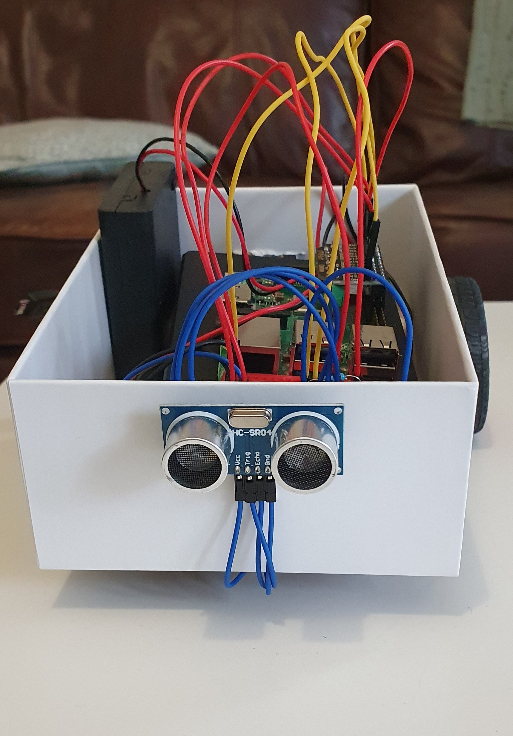
We think there are a few issues causing the robot to struggle to follow the line. First there was the weight issue, the large power bank was making it difficult to get the robot to move slowly and precisely. We think this is also true for the motors, we just don’t think they are quite up to the task. Once we removed the power bank it was a challenge to get the robot to make slow turns. We also think the chassis (the box) doesn’t help and the position of the line sensor. This isn’t the end for the line following though….We have ordered an exciting new chassis and slower more precise motors! The new chassis is smaller so I think our robot will be built using the Raspberry Pi Zero as it is a lot smaller and will take up less space. So exciting stuff to come, check back soon!
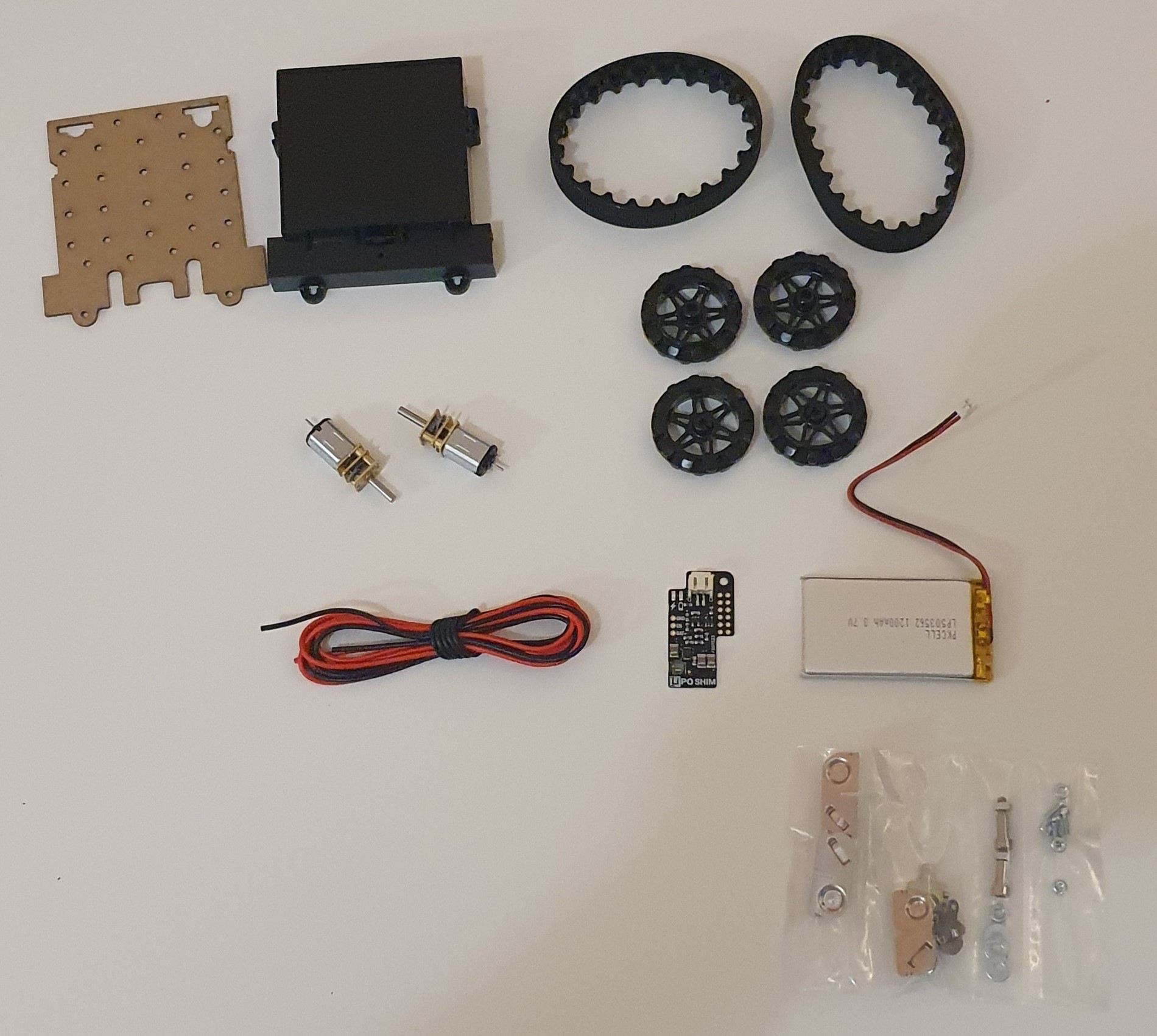
These are the new parts for our robot. Including a chassis with caterpillar tracks and new more precise motors.
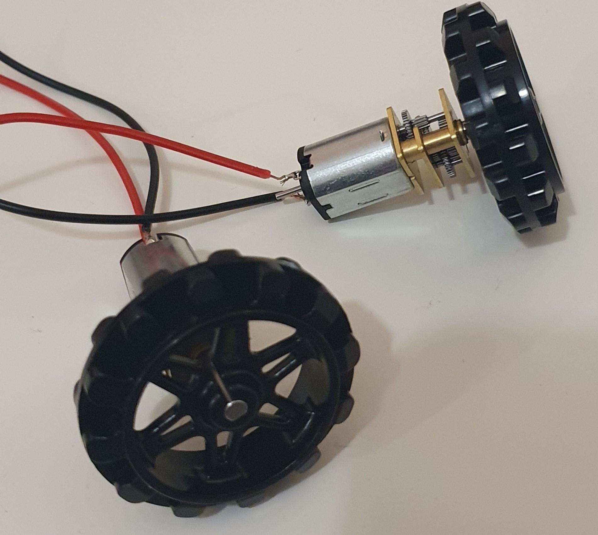
We first had to solder some wires to the motors. Solder is a type of metal that melts easily and is used to join electrical components.
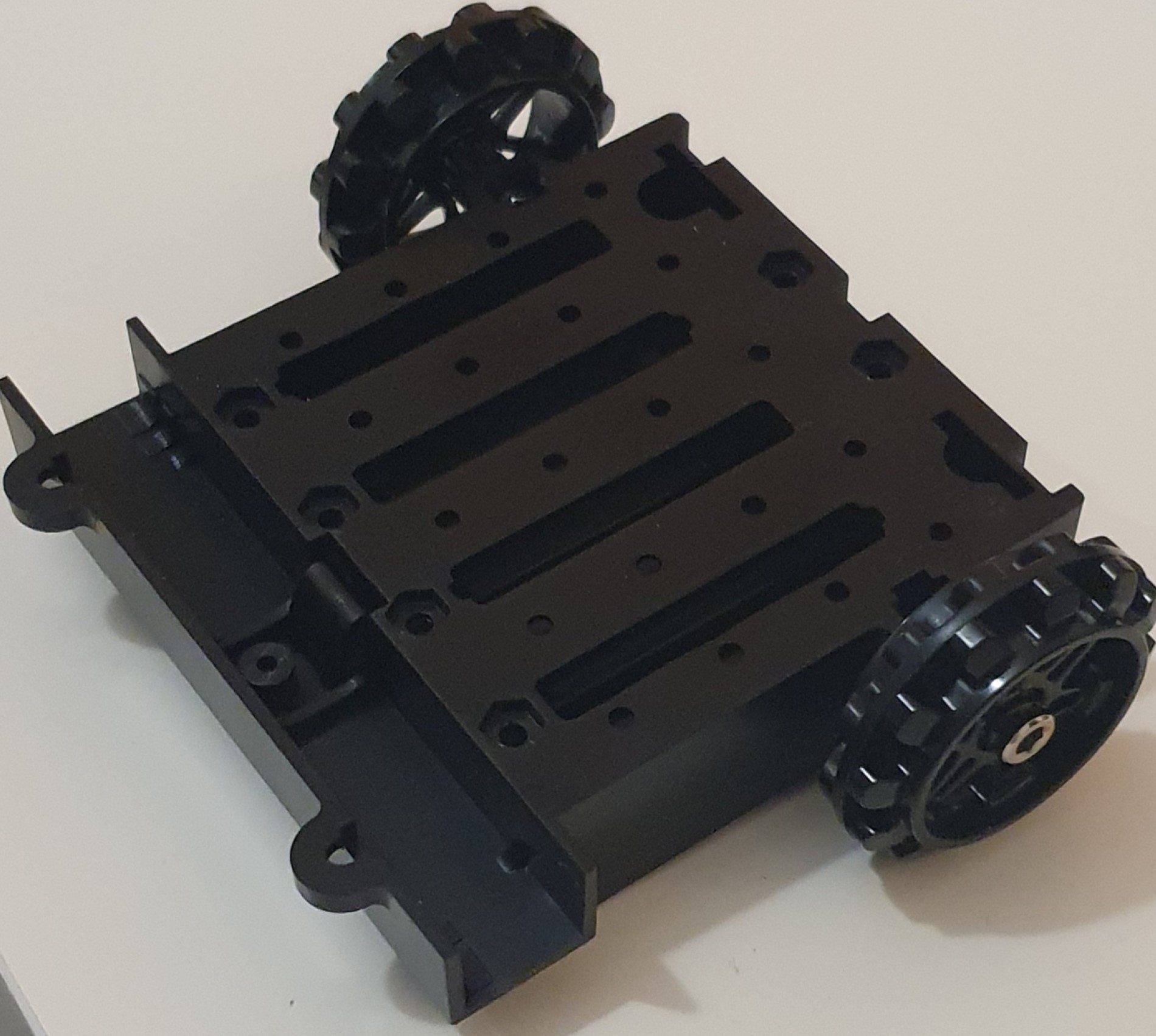
We then built the chassis.
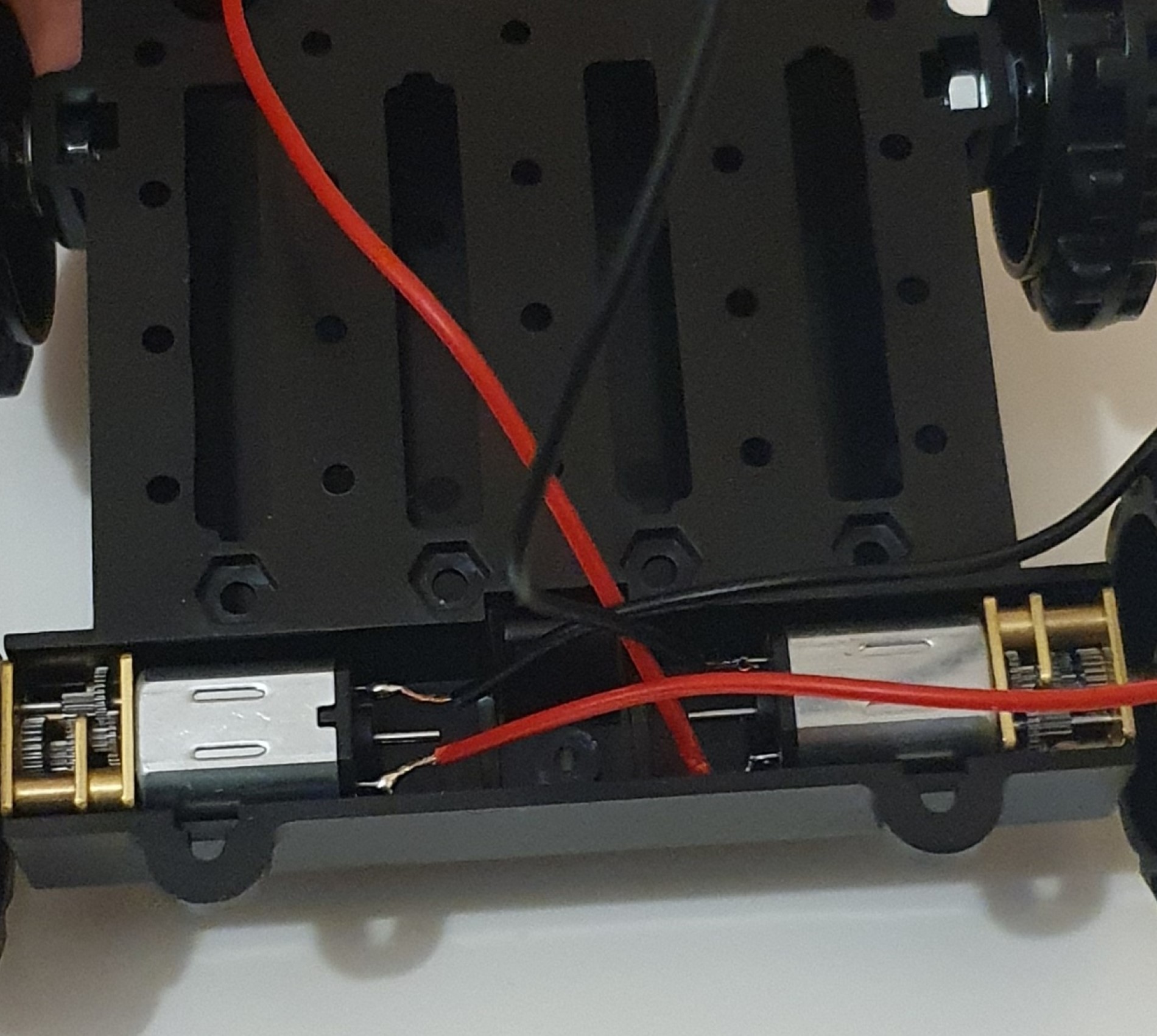
Put the motors in place in the chassis.
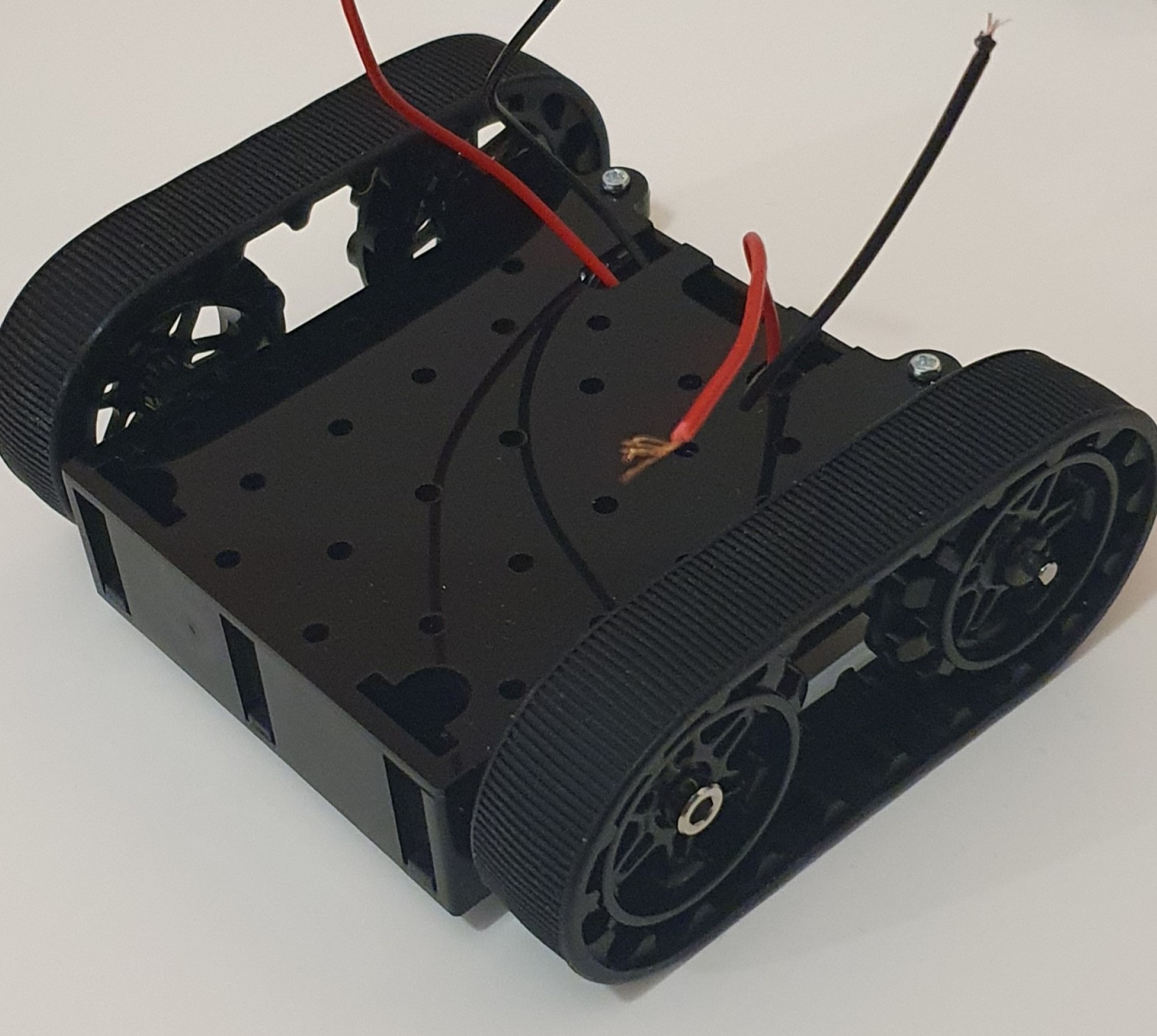
We then added the tracks and flipped it over and screwed on the mounting plate.
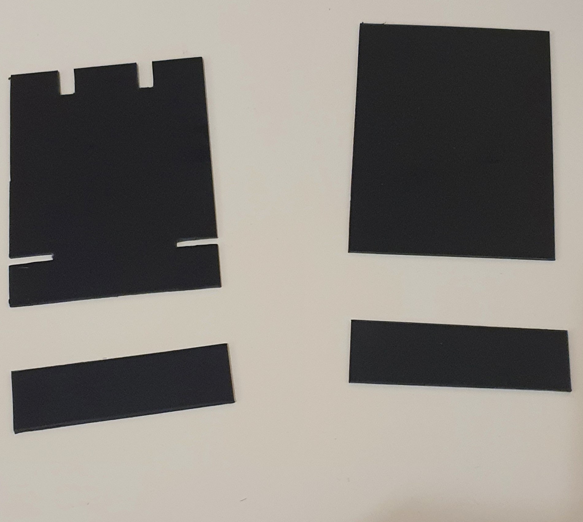
This time we made a custom casing for our robot out of plastikard (sheet plastic).
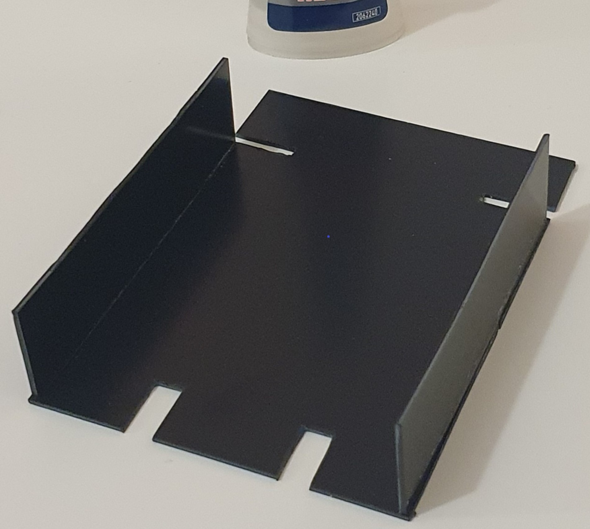
Here is the case all glued together minus the top piece.
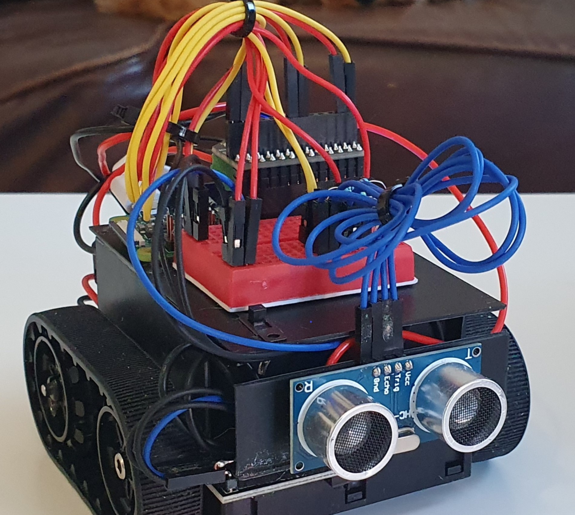
Here it is! We think he looks a lot better. He has a lockdown haircut, but don’t we all!